Description
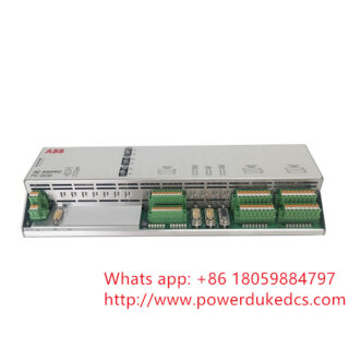
 The ABB 3BHL000986P7001 (internally designated alongside cross-references such as the LXN1604-6 platform) is a high-reliability, ruggedized industrial AC/DC switching power supply module. Functioning within demanding electrical topologies—including mid-to-high power industrial rectifier corridors and specialized ABB excitation or drive sub-assemblies—this module acts as a key component to supply a stable, low-ripple continuous 24 V DC power rail directly to internal control logic networks and interface processing modules.
Technical Specifications
| Parameter | Value / Detail |
| Model Number | 3BHL000986P7001 |
| OEM Cross-Platform Reference | LXN1604-6 Family Series |
| Input Supply Voltage (AC Range) | 85 to 264 V AC (Universal continuous tolerance, 47 to 63 Hz) |
| Input Supply Voltage (DC Range) | 90 to 350 V DC compatible input stage |
| Nominal Output Parameters | 24.7 V DC output rating |
| Maximum System Power | 500 W structural output ceiling |
| Redundancy & Sharing Support | Active parallel load sharing via independent internal decoupling diodes |
| Electrical Isolation Barrier | 3 kV AC maximum galvanic separation (Input to Output) |
| Mounting Orientation Footprint | Direct symmetrical 35 mm DIN-rail hardware clip assembly |
| Storage Temperature Range | −25 to +70 °C (−13 to +158 °F) |
| Relative Operating Humidity | 5% to 95% baseline (non-condensing atmospheric envelope) |
Technical Features & Field Engineering Context
Rectangular Current Overload Dynamics
Unlike commodity-grade power distribution blocks that experience internal hiccup-mode cycling during localized current spikes, the 3BHL000986P7001 utilizes a robust rectangular current limiting methodology. Under heavy inrush states—such as charging highly capacitive DC input filters or firing high-draw physical trip relays—the module controls its voltage output down along a defined power curve while delivering full rated current. This prevents the primary 24 V logic rail from collapsing entirely during minor transient field anomalies, eliminating spurious control-chassis resets.
Thermal Dissipation and Cabinet Placement
The physical construction of the housing relies on natural chimney convection for component cooling.
- Vertical Mounting Limits: When mounted vertically on standard 35 mm DIN rails, the internal thermal balance remains compliant up to +40 °C ambient room temperature under full rated load conditions.
- Horizontal Layout Constraints: If regional spatial limitations demand a horizontal installation profile, the maximum continuous thermal ceiling drops to +55 °C and the total system load must be derated by approximately 25% to account for reduced airflow across internal power semiconductor grids.
Galvanic Shielding and Harmonic Protection
The input stage incorporates an active Power Factor Correction (PFC) network alongside dual-stage electromagnetic interference (EMI) suppressors. During 2 AM commissioning phases near high-power variable frequency drives (VFDs) or heavy phase-controlled rectifiers, this shielding matrix blocks line harmonics from bleeding through to sensitive diagnostic analog I/O loops tied downstream.
Commercial and Logistics Status
- Condition: New Original (New Surplus) inside intact OEM protective factory packaging, or Refurbished (fully certified on dynamic electronic load test fixtures).
- Warranty Period: 12-month operational and assembly warranty from the official date of logistics tracking export.
- Global Lead Time: Standard stock inventory parameters ship within 2 to 4 business days via expedited air freight.
- Documentation: Ensure visual verification of identical production series codes and revision tags on your existing dead module before running hot-swap replacements in operational drive cabinets.
Commercial Note: The 3BHL000986P7001 is a specialized industrial part whose global spot market cost varies based on immediate power-generation sector turnarounds and strategic maintenance cycles. The listed pricing represents an indicative target value; contact our technical sales desk for a formal, time-bound commercial quotation.
Frequently Asked Questions
Is the 3BHL000986P7001 interchangeable with standard generic LXN1604-6 modules sourced outside ABB?
Mechanically and electrically, the units share identical core platforms. However, specific 3BHL configurations feature targeted conformal coating metrics on the printed circuit board traces to resist tracking failures within corrosive gaseous atmospheres (such as sulfur or heavy humidity profiles). Always cross-reference your system’s exact environmental certification criteria before deploying non-ABB branded alternatives.
What terminal protocol is utilized to configure parallel load balancing between two units?
The output faceplate features designated inter-module parallel balance connection points. Tying these auxiliary line matching pins together bridges the inner reference voltage loops, prompting both units to balance output currents equally and avoiding uneven heat loads that degrade components prematurely.
How do I troubleshoot a complete dark-panel indication on this module?
First, isolate primary input power and inspect the internal primary input fuse link. If the line side registers a clean 220 V AC input but the output diagnostic LEDs remain unlit, check the external 24 V line for physical short circuits. The built-in electronic protection layer will suppress output drive if it identifies a permanent short circuit down the line.