

Description
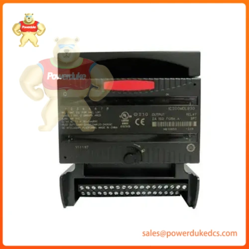 1. Unboxing & Physical Snapshot
-
Model & Brand: GE Fanuc / Emerson VersaMax Series — 16-Point Isolated Relay Output Module, Part Number IC200MDL930J-700 (Base Model: IC200MDL930, Revision J, Custom/Bulk Logistics Suffix “-700”).
-
Physical Dimensions: Standard VersaMax modular I/O carrier-mount profile (approx. 110 mm x 66.8 mm x 50.0 mm).
-
Estimated Shipping Weight: 0.45 kg (Including protective anti-static packaging and heavy-duty logistics carton).
-
What’s in the Box: IC200MDL930J-700 module assembly featuring 16 isolated form A (normally open) relay output channels, front-panel status LEDs for point ON/OFF states and backplane power (
OK), backplane connector pins, and conformity insert. (Note: The snap-together I/O carrier base is ordered separately).
2. Product Introduction
Engineered for heavy-duty industrial automation applications, this discrete relay output module provides flexible switching capabilities for both AC and DC control loads—including solenoid valves, contactors, indicator lamps, and minor motor starters.
Fitted onto a standard VersaMax snap-together carrier base inside an industrial control panel, the hardware uses individual electromechanical relays to deliver complete galvanic isolation between internal PLC logic and external field devices. (Plant automation engineers rely on this robust relay tier to safely switch mixed voltage levels without risking backplane damage.)
3. Core Technical Specifications
| Parameter | Value |
| Product Family | GE Fanuc / Emerson VersaMax I/O System |
| Module Type | 16-Point Isolated Relay Output Module |
| Output Type | Form A (Normally Open) Electromechanical Relays |
| Switching Voltage Range | 5 to 30 VDC or 5 to 250 VAC (47–63 Hz) |
| Maximum Current per Point | 2.0 A resistive load per output point |
| Total Module Current Limit | Up to 8.0 A continuous common load limit |
| Response Time | 10 ms maximum (ON and OFF switching cycle) |
| Backplane Power Draw | 130 mA maximum from +5V bus |
| Operating Temperature | 0°C to +60°C (+32°F to +140°F) |
| Mounting Style | DIN-rail mount via VersaMax snap-together I/O carrier base |
4. Global Compliance & Industry Certifications
Auditors and safety compliance officers overseeing industrial control panels enforce strict isolation and switching standards for electromechanical output hardware.
-
Expected Certifications: CE Mark, UL Listed, UL HazLoc Class I Division 2 hazardous location ratings, and RoHS environmental compliance.
-
Safety Relevance: Complete relay channel-to-channel and channel-to-backplane electrical isolation prevents high-voltage field transients from bridging into low-voltage internal PLC controller paths.
-
Audit Directive: Verify specific lot tracking and revision tags. Ensure the hardware suffix and revision code (Revision J) align precisely with the plant’s approved electrical schematics and safety validation files.
5. Long-Term Storage & Asset Preservation Guide
Discrete relay output modules kept in warehouse reserve stock degrade prematurely if environmental baselines are neglected.
-
ESD Protection Integrity: Keep the electronic module sealed inside its original metallized anti-static shielding bag to protect internal CMOS logic circuits from electrostatic discharge.
-
Climate Management: Maintain warehouse storage relative humidity strictly below 95% non-condensing, avoiding rapid thermal shifts that invite internal micro-condensation on relay contacts.
-
Mechanical Care: Protect the multi-pin connector interface on the rear of the module from physical impact or bending by storing units upright in standard slots or protective logistics foam trays.
6. Physical Installation Prerequisites
Proper mechanical carrier seating and wiring discipline are mandatory to maximize relay contact lifespan and prevent premature mechanical failure.
-
Inductive Load Suppression: Always install flyback diodes across DC inductive loads (solenoids/relays) or RC snubbers across AC loads. Unsuppressed inductive kickback will rapidly pit and weld mechanical relay contacts shut.
-
Carrier Alignment: Snap the module securely onto its designated VersaMax I/O carrier base, ensuring steady, balanced pressure so the rear pins engage cleanly without bending.
-
Current Capacity Check: Verify that total aggregate current drawn across common terminal groups does not exceed the 8.0 A module maximum threshold under full operating load.
7. Buyer’s FAQ (Logistics & Compliance Focus)
Q: What Harmonized System (HS) Tariff Code applies to global shipments of this relay output module?
A: Industrial programmable logic controller input/output modules typically clear under HS Code 8537.10 (Boards, panels, consoles for electrical control or distribution of electricity) or 8538.90. Confirm exact sub-headings with your customs broker.
Q: Does importing this VersaMax spare part require an authentic Certificate of Origin (COO)?
A: Yes. Securing a formal Certificate of Origin from your vendor verifies manufacturing traceability, which is vital for quality assurance compliance and customs clearance.
Q: What happens to the relay outputs if communication with the PLC CPU is lost?
A: The module can be configured via programming software to either hold its last recorded operational state or safely default all relay channels to the open (OFF) position upon communication timeout.






