

Description
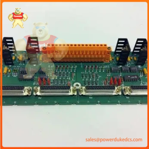
- Model & Brand: General Electric (GE) Mark V Series DS200XDSAG1A (Transducer Interface / LM Fuel Pressure Management Board – XDSA)
- Physical Dimensions: Standard Mark V printed circuit board profile (Approximate 33.0 cm x 17.8 cm chassis mount footprint)
- Estimated Shipping Weight: 0.5 kg (Packaged in multi-layer anti-static ESD shielding and structural foam carton)
- What’s in the Box: XDSA terminal printed circuit card, normal PCB coating assembly, onboard jumper configuration blocks, and factory inspection test sheet.
Accurate fuel pressure regulation and real-time gas turbine monitoring underpin the safe and stable operation of heavy power generation assets. System engineers mount this Transducer Interface (XDSA) terminal board directly within GE Speedtronic Mark V turbine control enclosures, bridging smart pressure transducers (such as Honeywell LG-1237 units) with the core control architecture via DB-25 connectors and RS-422 serial links (—which is vital for preventing fuel supply anomalies and maintaining stable combustion parameters in heavy-duty gas turbine packages).
Technicians must verify proper jumper configurations for RS-422 line termination and sensor addressing prior to powering up the rack to prevent serial communication collisions across redundant control sectors.
| Parameter | Value |
| System Platform | GE Speedtronic Mark V Turbine Control System |
| Module Type | Transducer Interface Terminal Board (XDSA) / LM Fuel Pressure Management Board |
| Primary Function | Interface for smart pressure transducers via serial communication and 12 VDC power delivery |
| Communication Interface | RS-422 multi-drop serial links via terminal blocks and DB-25 ports |
| Power Supply Input | 12 VDC nominal (supplied via DPWA terminal boards) |
| Operating Temperature | -40°C to +85°C ambient panel enclosure range |
| PCB Construction | Surface mount technology with standard protective coating |
Auditors inspecting critical power generation and turbine control racks demand rigorous documentation verifying electrical safety, isolation, and environmental operating limits.
- CE Mark: Confirms conformity with European Union directives covering electromagnetic compatibility (EMC) and low-voltage safety.
- UL / cUL Recognized: Validates North American industrial standards for internal control and automation sub-assemblies.
- RoHS Compliance: Restricts hazardous chemical substances in electronic component manufacturing.
Compliance Note: A recognized industrial hardware rating ensures that internal circuit trace separations and voltage-suppression architectures prevent transient fault propagation during high-energy plant events. Verify specific system compliance certificates with GE prior to annual regulatory safety audits.
Dormant turbine control cards sitting in warehouse stockroom bins face terminal oxidation, component aging, and semiconductor degradation if environmental parameters escape strict control limits.
Keep the circuit board sealed tightly inside its original anti-static (ESD) moisture-barrier bag to safeguard internal logic microchips and serial transceivers from electrostatic discharge. Maintain warehouse storage temperatures between -40°C and +85°C with relative humidity kept strictly below 95% non-condensing to prevent micro-corrosion on edge connector fingers and terminal blocks. Ensure the hardware remains protected from heavy physical drop forces that could fracture the multi-layer printed circuit substrate.
Chassis slot allocation and secure backplane mounting dictate precise physical placement inside the turbine control cabinet. Ensure all system power sources are locked out (LOTO) prior to handling. Secure the board firmly to its designated chassis mount standoffs, verifying that stab-on ground connections at each end of the board maintain low-impedance shielding continuity with the cabinet enclosure.
- What is the correct HS Tariff Code for international customs clearance?Industrial turbine control and interface printed circuit boards classify under harmonized code 8538.90.8180, though verify exact regional rulings with your broker.
- Does this XDSA terminal board require pre-loaded system firmware?Hardware assembly DS200XDSAG1A functions primarily as a passive/active terminal and signal conditioning subassembly; specific sensor polling parameters are managed by the Mark V controller software.
- How does the Country of Origin (COO) impact global trade compliance?The verified COO dictates trade agreement qualification and must match commercial shipping paperwork to eliminate border customs clearance delays.
- Why is comprehensive transit insurance mandatory for this component?Precision-mounted surface components, DB-25 connectors, and delicate multi-layer circuit traces can suffer structural micro-fractures or pin bending under severe drop impacts during freight transit.






