

Description
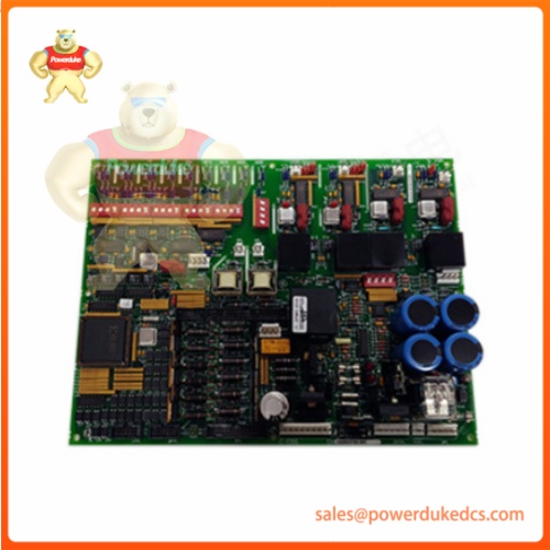
1.Unboxing & Physical Snapshot (Dynamic List)
- Model & Brand: GE DS200DCFBG1BNC
- Physical Dimensions: 140 mm x 160 mm x 20 mm (Approximate W x H x D)
- Estimated Shipping Weight: 0.5 kg (Packaged in multi-layer anti-static bubble wrap and corrugated carton)
- What’s in the Box: Green printed circuit board assembly, onboard BNC coaxial connector, pluggable terminal blocks, and factory inspection document.2.Product IntroductionSustained ambient heat and relentless electrical noise challenge every delicate circuit trace inside heavy-duty power conversion cubicles. Shielding internal feedback loops against high-frequency transformer spikes requires specialized regulation hardware built to operate reliably under extreme thermal stress (—which is critical for continuous turbine excitation cabinets).
Technicians slide this printed circuit board directly into the designated rack slot, securing the gold-plated edge fingers into the backplane connector. Maintain proper grounding discipline during wiring to prevent ground loops from corrupting critical analog feedback signals.
3.Core Technical Specifications
| Parameter | Value |
|---|---|
| Input Power (AC) | 38 to 115 VAC, 47 to 63 Hz |
| Auxiliary Input Voltage | ±24 VDC for internal rails |
| Max Output Current | 10 A on 24 VDC channel |
| Voltage Regulation | ±1% zero to full load |
| Output Ripple | 150 mVp-p maximum |
| Analog Input Ranges | 0–5 VDC, 0–10 VDC, 4–20 mA DC |
| BNC Connector Impedance | 75 ohms coaxial interface |
| Operating Temperature | -40°C to +70°C ambient range |
| Vibration Profile | 5–2000 Hz random vibration |
- Global Compliance & Industry CertificationsAuditors demand verifiable paperwork for power electronics governing high-energy generator excitation loops. This control board meets major regulatory benchmarks.
- CE Mark: Validates conformity with European Union directives covering electromagnetic compatibility and low-voltage operation.
- UL/cUL Recognized: Confirms component safety standards for industrial control panels across North America.
- ATEX / IECEx: Permits deployment in hazardous Class I Division 2 areas when housed within purged electrical enclosures.
- RoHS Compliance: Restricts hazardous substances during electronic card fabrication.
Compliance Note: A UL component recognition rating ensures internal trace clearances prevent electrical flashover during high-voltage transients. Verify specific lot conformity directly with GE prior to plant safety audits.
5.Long-Term Storage & Asset Preservation Guide
Spare electronic assemblies sitting dormant in warehouse bins face electrolytic capacitor dry-out and micro-corrosion if environmental controls fail. Asset managers must enforce strict preservation routines.
Keep the circuit board sealed inside its original anti-static (ESD) moisture-barrier bag to shield sensitive surface-mount integrated circuits from static discharge. Maintain warehouse storage temperatures between 10°C and 30°C with relative humidity kept strictly below 60% to prevent oxidation on the gold-plated connector fingers. If inventory records indicate the unit has rested on a shelf past 24 months, execute a controlled variable-voltage bench test to safely reform the onboard electrolytic capacitors prior to live cabinet installation.
6.Physical Installation Prerequisites
Rack cooling dynamics dictate precise physical placement inside the control enclosure. Leave at least 50mm of open vertical space above and below the board chassis to allow natural convection airflow across the active component side. Fasten the retaining screws securely to the metal sub-rack to maintain low-impedance high-frequency ground continuity.
- Buyer’s FAQ (Logistics & Compliance Focus)
- What is the correct HS Tariff Code for international customs clearance?Industrial electronic controller cards classify under harmonized code 8538.90.8180, though verify exact regional rulings with your broker.
- Does this replacement power board ship with pre-loaded configuration firmware?Hardware assembly DS200DCFBG1BNC functions as a passive/active analog feedback and regulation board requiring no user-loadable firmware.
- How does the Country of Origin (COO) impact global trade compliance?The verified COO determines eligibility for regional trade preferences and must match commercial shipping paperwork to eliminate border customs holds.
- Why is comprehensive transit insurance mandatory for this component?Delicate surface-mount transformers and coaxial connectors can suffer mechanical micro-fractures under heavy drop impacts during express freight shipping.






