

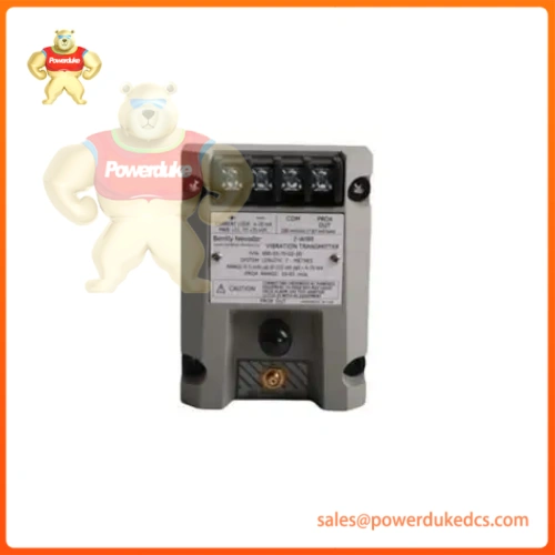
Description

- Model & Brand: Bently Nevada (Baker Hughes) / 990 Series (Catalog No. 990-05-50-01-00 / 2-Wire Vibration Transmitter)
- Physical Dimensions: Compact DIN rail-mountable housing profile (Approx. 7.6 cm × 10.2 cm × 6.3 cm module layout)
- Estimated Shipping Weight: 0.50 kg (Packaged in multi-layer anti-static ESD shielding and structural foam carton)
- What’s in the Box: 990 vibration transmitter unit, 5.0-meter system length option, 35 mm DIN rail mounting clips, and factory calibration inspection sheet.
Original equipment manufacturers (OEMs) of centrifugal air compressors, industrial pumps, motors, and auxiliary fans require compact, reliable vibration monitoring solutions that interface seamlessly with standard control architectures without necessitating complex rack-based monitor setups. System engineers integrate the Bently Nevada 990 2-Wire Vibration Transmitter (Catalog No. 990-05-50-01-00) directly into balance-of-plant skids and local control panels, accepting signals from an integral proximity probe system to condition shaft relative vibration into a proportional 4–20 mA loop-powered signal (—which is vital for feeding real-time vibration telemetry directly into plant PLCs or distributed control systems for continuous health trending).
Cabinet technicians must ensure proper probe gapping (0.5 to 1.75 mm from target) and robust signal shielding continuity to prevent electromagnetic interference from distorting the current loop output.
| Parameter | Value |
| System Platform | Bently Nevada 990 Series Machinery Protection & Monitoring |
| Module Type | 2-Wire Vibration Transmitter (Model 990) |
| Full-Scale Option (-05) | 0 to 5 mils pp (0 to 125 µm pp) peak-to-peak vibration amplitude |
| System Length Option (-50) | 5.0 metres (16.4 feet) total system length (Probe and extension cable) |
| Mounting Option (-01) | 35 mm DIN rail clips |
| Agency Approval Option (-00) | Standard general-purpose configuration (Haz. location approvals not specified) |
| Input Power | +12 to +35 VDC loop power at transmitter terminals |
| Signal Output | 4 to 20 mA proportional to full-scale vibration range |
| Frequency Response | 5 Hz to 6,000 Hz (+0, -3 dB) |
| Operating Temperature | -35°C to +85°C (-31°F to +185°F) potted transmitter enclosure range |
| Enclosure Protection | IP20 industrial DIN rail housing module |
Auditors inspecting skid-mounted auxiliary machinery and balance-of-plant control loops demand rigorous documentation verifying electrical safety, environmental ruggedization, and signal isolation standards.
- CE Mark: Confirms conformity with European Union directives covering electromagnetic compatibility (EMC) and low-voltage safety.
- General Purpose Compliance: Manufactured in accordance with industrial safety specifications for non-hazardous locations (dependent on explicit regional agency selections).
- IEC / ISO Standards: Complies with international specifications for rotating machinery vibration transducers and signal conditioners.
- RoHS Compliance: Restricts hazardous chemical substances in electronic component manufacturing.
Compliance Note: Compliance with industrial EMC guidelines ensures that loop-powered 4–20 mA transmission lines remain stable under heavy industrial electrical noise. Note that vibration transmitters provide overall trending data but lack advanced phase analysis or multi-parameter diagnostic functions found in full rack-based monitoring systems.
Dormant vibration transmitters stored in warehouse stockroom bins face terminal corrosion and internal component aging if environmental parameters escape strict control limits.
Keep the transmitter sealed tightly inside its original anti-static (ESD) moisture-barrier bag to safeguard internal signal-conditioning microcircuits from static discharge. Maintain warehouse storage temperatures between -51°C and +100°C with relative humidity kept strictly below 95% non-condensing to prevent micro-corrosion on terminal connection points. Ensure the hardware remains protected from heavy physical drop forces that could compromise the housing substrate.
DIN rail structural stability and probe gap alignment dictate precise physical placement inside the local control panel. Ensure all loop power feeds are completely locked out (LOTO) prior to wiring. Mount the transmitter module securely using the 35 mm DIN rail clips (-01), route the proximity probe cable carefully avoiding sharp pinch points, and calibrate zero/span potentiometers only after verifying correct mechanical probe gap settings.
- What is the correct HS Tariff Code for international customs clearance?Industrial vibration measuring instruments and electronic transmitters classify under harmonized code 9031.80.8085 (or regional equivalent 9031.80), though exact regional rulings should be verified with your broker.
- Does this vibration transmitter require separate external power supply modules?No, hardware assembly 990-05-50-01-00 operates as a 2-wire, loop-powered device driven directly by a +12 to +35 VDC source across the 4–20 mA current loop.
- How does the Country of Origin (COO) impact global trade compliance?The verified COO (USA) dictates trade agreement qualification and must match commercial shipping paperwork to eliminate border customs clearance delays.
- Why is comprehensive transit insurance mandatory for this component?Precision internal signal processing filters, integrated terminal blocks, and attached proximity probe leads can suffer structural strain or internal micro-fractures under severe drop impacts during freight transit.






