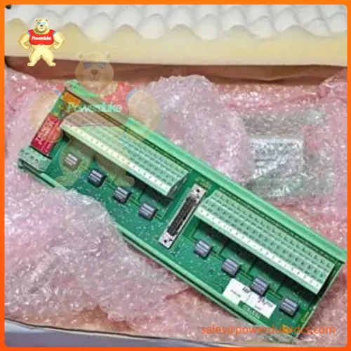
Description
The MVAX12R1CB0756A is an auxiliary, attracted-armature protective relay configured specifically for trip circuit supervision (TCS). Manufactured historically under the Alstom, GEC Alsthom, and Areva brands—and currently supported under GE Vernova’s grid solutions portfolio—this module monitors the health and integrity of a high-voltage circuit breaker’s tripping supply. If the control voltage drops below the operating threshold or a complete supply failure occurs, the relay de-energizes to trigger immediate visual and audible alarms in the substation control system.
Commercial Availability & Procurement Details
- Condition: New Original (New Surplus) or Refurbished (Fully Bench Tested) available
- Availability: In stock, typical lead time is 1 to 2 business days
- Warranty: 12-month comprehensive warranty
- Pricing Note: Price is dependent on current legacy inventory tiers and regional supply. Contact our sales office for a binding, itemized quote.
Technical Specifications
| Parameter | Value |
| Model Number | MVAX12R1CB0756A |
| Relay Family | MVAX Series (MVAX 12 Type) |
| Monitored Fault Profile | Failure of trip supply only (Single-unit configuration) |
| Rated Auxiliary Voltage (V_x) | 110 to 125 V DC (Operating range: 87.5 to 137.5 V DC) |
| Drop-off Voltage Threshold | Approx. 40% of nominal rated voltage |
| Pick-up Voltage Threshold | < 80\% of nominal rated voltage |
| Typical Operating/Reset Time | < 30 ms |
| Built-in Time Delay | 100 ms delayed drop-off (via internal RC circuit) |
| Contact Configuration | 2 Contacts (Normally Open/Normally Closed configurations) |
| Burden (Power Consumption) | 15 mA nominal / 1.9 W maximum at 125 V DC |
| Case Size | Size 2 standard flush/panel mount enclosure |
| Mechanical Flag | Available hand-reset operation indicator flag |
Engineering Application & Integration Constraints
Circuit Implementation
Unlike the more complex MVAX21 or MVAX31 relays—which monitor the entire trip path including the trip coil wiring and auxiliary switches in both open and closed positions—the MVAX12 is strictly designed to monitor the integrity of the trip supply itself. It is wired in parallel directly across the DC fuse/breaker distribution bus feeding the breaker mechanism.
Immune to Spurious Transients
A 100 ms resistance-capacitance (RC) delayed drop-off network is factory-integrated within the MVAX12 hardware. This delay prevents the relay from dropping out and triggering false alarms during short-duration system voltage dips caused by heavy fault currents elsewhere on the network, or during normal battery charger load transitions.
Field Engineering Note: When performing insulation or dielectric strength testing (Megger tests) on the protection panel, always isolate or completely pull out the MVAX12 module from its case. The internal capacitors within the 100 ms delay block retain charge and can be damaged or give false leakage readings under high-voltage testing conditions.
Frequently Asked Questions
What happens if the DC supply voltage degrades slowly instead of failing catastrophically?
The MVAX12 contains an attracted-armature mechanism calibrated to drop off positively without “chatter” or intermediate contact fluttering when the voltage declines below approximately 40% of the nominal rating (< 44 V DC on a 110 V base). It will not pick back up until the DC bus restores to at least 80% of nominal (> 88 V DC), enforcing a solid hysteresis band.
Can this specific model be used on a 220 V DC control bus?
No. The suffix part number designates this unit for 110/125 V DC systems. Connecting it directly to a 220/250 V DC control network will overload the internal coil, causing insulation failure and permanent thermal damage due to excessive burden. Always match the voltage window specified on the relay side-label.
How do I manually verify if the relay contacts have failed?
Isolate the DC supply by removing the inline panel fuses, pull the relay forward onto a test bench, and use an ohmmeter to check terminal resistance. For a standard 110/125 V 2-contact configuration, the expected coil resistance should measure within \pm 10\% of 10,370\ \Omega. Any wide deviation or an open-circuit measurement indicates a degraded or burnt-out internal coil assembly.