Description
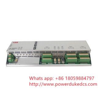
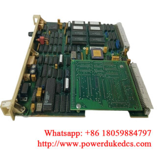
The ABB SDCS-PIN-51 (part number: 3ADT220090R0006) is a specialized power circuit interface and scaling measurement board utilized within ABB’s heavy-duty industrial DC drive and rebuild platforms—most notably the DCS800, DCS550, and legacy DCS500 series. Functioning as the core diagnostic and coordination link between the high-power thyristor bridge and the low-voltage control electronics, it acts as a measuring, gate-driver interface, and synchronization node for the drive.
Technical Specifications
| Parameter | Value / Specification |
| Brand / Manufacturer | ABB |
| Model / Part Number | SDCS-PIN-51 / 3ADT220090R0006 |
| Product Classification | Main Power Interface / Scaling & Measuring Board |
| Compatible Drive Platforms | DCS800, DCS550, DCS500, and DCS800-R Rebuild/Modernization Kits |
| Measurement Architecture | High-ohmic voltage sensing (5\ M\Omega standard for 500 V systems) |
| Isolation Barrier | Galvanic isolation between power stack and control framework |
| Input Logic Supply | 24 V DC via ribbon cabling harness |
| Physical Termination Links | 16-pole and 20-pole flat interface ribbon connectors |
| Operating Temperature | 0 to +55\ ^\circC (+32 to +131 ^\circF) |
Commercial and Availability Logistics
- Product Condition: Available as New Original (New Surplus) or Certified Refurbished (fully checked and load-calibrated using dynamic industrial drive testing rigs).
- Warranty: 12-month technical warranty covering physical PCB integrity, gate triggering outputs, and measuring resistors.
- Availability: In stock. Handling and worldwide dispatch through priority logistics channels take 2 to 4 business days.
- Pricing Notice: Price varies based on supply availability, factory lifecycle support changes, and active system emergency requirements. Contact our sales department for a formal quote.
Engineering Considerations and Field Deployment Notes
Voltage Scaling and Mains Synchronization
The primary responsibility of the SDCS-PIN-51 is monitoring actual AC mains input voltage and DC output voltage loops via high-ohmic 5\ M\Omega resistor paths. This real-time voltage tracking allows the centralized driver processor to accurately calculate phase angles for thyristor firing pulses. If configuring the unit for non-standard, small-voltage conditions (< 100 V), external rescaling boards (such as the SDCS-SUB-4) or modified matching resistors must be implemented to maintain measurement resolution and prevent mains synchronization drift.
Grounding Potentials and Component Mating
When installing the module as part of a DCS800-R rebuild or servicing an open drive enclosure, the mechanical mounting screws serve as a critical path to the main system chassis ground.
- Ensure the mounting standoffs are completely clean and free of corrosion or paint.
- Verify that the mechanical fixing points of both the SDCS-PIN-51 board and the adjacent SDCS-PIN-48 pulse transformer card share the exact same ground potential.
- Unbalanced grounding points allow voltage differences to build up, introducing high-frequency noise into the delicate Current Transformer (CT) measurement lines (terminating at block X25).
Ribbon Cable Routing and Shielding Rules
Control links connecting the main electronics to ports X12 and X13 on the PIN-51 board rely on high-density flat ribbon cables. These signals are highly sensitive to electromagnetic induction. Avoid routing these ribbon harnesses parallel to high-current thyristor busbars or heavy motor phase lines. Twist or loop cable pairings appropriately and verify that all ribbon shields are securely connected on both ends to prevent random firing faults or gate-driver timeout errors.
Frequently Asked Questions
What other auxiliary boards connect directly to the SDCS-PIN-51?
In typical modernization and build configurations, an SDCS-REB-1 board plugs directly into the PIN-51 card (mating across ports X513, X113, and X213). A 20-pole flat ribbon cable then routes out from port X613 on the REB-1 card to feed the trigger loops on the SDCS-PIN-48 pulse transformer matrix.
How do I run safe diagnostic testing on this module without a live motor attached?
For troubleshooting or commissioning testing, you can simulate safe temperature values and bypass field sensor faults by plugging a dedicated 2.21\ k\Omega resistor directly into the X22 terminal block on the interface assembly.
What symptoms indicate that the scaling resistors on the board have failed?
If the scaling resistors break or experience thermal drift, the drive’s control screen will typically show continuous “Mains Supply Faults,” phase loss warnings, or highly unstable DC voltage readings even when incoming line power is perfectly balanced.
Technical Notice: High voltage remains present inside DC drive enclosures long after the primary mains breaker is tripped. Always verify that phase inputs U1, V1, W1 and busbars C+ and D- have dropped completely to zero volts relative to the frame using a certified multimeter before performing card swaps or touching termination
plugs.