Description
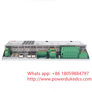
The ABB REJ603BB401NN31E is a self-powered numerical feeder protection relay designed for overcurrent and earth-fault protection in secondary distribution networks. It operates primarily within medium-voltage switchgear environments, functioning without an external auxiliary power supply by deriving its operating energy directly from the primary current transformers (CTs).
Commercial Supply Status
- Condition: New Original (New Surplus), Factory Sealed
- Availability: In stock
- Lead Time: 1–3 business days
- Warranty: 12 months
- Pricing Note: Price subject to market conditions; contact us for a firm quote.
Field Engineering & Integration Notes
In field deployments across medium-voltage substations, the REJ603 series is frequently paired with specific low-power current transformers (Rogowski coils or conventional CTs depending on the hardware variant code). The “BB” configuration denotes specific CT input characteristics and trip coil output ratings; engineers must verify that the trip output matches the energy requirements of the switchgear’s magnetic actuator or low-energy trip coil.
Because this relay is self-powered, it requires a minimum primary threshold current (typically around 0.1 to 0.2 times the nominal current) to boot the processor and enable protection functions. When commissioning or using secondary injection test sets, ensure the test set can supply sufficient burden to power up the unit before executing trip timing tests.
Technical Specifications
| Parameter | Value |
| Product Type | Self-Powered Overcurrent & Earth-Fault Protection Relay |
| Model Code Breakdown | REJ603 Variant BB, Hardware Configuration 401NN31E |
| Power Supply | Self-powered via current measurement circuits (no auxiliary voltage required) |
| Protection Functions | 3-phase overcurrent (50/51), Earth-fault (50N/51N), Thermal overload (49F) |
| Measurement Inputs | 3 x Phase current inputs, 1 x Earth current input |
| Trip Output Type | Low-energy pulse output (designed for sensitive trip coils/actuators) |
| Binary Inputs / Outputs | Configuration dependent (verify schematic configuration with OEM datasheet) |
| User Interface | Integrated LCD with navigation push-buttons and LED status indicators |
| Enclosure Rating | IP54 (front panel integrated into switchgear door) |
| Operating Temperature | −25 to +55 °C |
| Storage Temperature | −40 to +70 °C |
Configuration & Protection Characteristics
The unit executes protection algorithms compliant with international standard curves:
- Definite Time (DT): Selectable delay settings from 0.05 s to 100 s.
- Inverse Definite Minimum Time (IDMT): Supports IEC 60255-3 curves (Normal Inverse, Very Inverse, Extremely Inverse) and specialized curves for fuse coordination.
- Fault Recording: Built-in non-volatile memory stores recent fault data and trip indicators, allowing local diagnostics on the LCD interface after a line de-energization event.
Frequently Asked Questions
- Q: Can this specific relay be powered by an external 24 V DC or 220 V AC/DC substation battery?
- A: The REJ603BB401NN31E is designed inherently as a self-powered relay utilizing energy from the CT circuits. While some variants in the REJ603 family offer auxiliary power inputs as a backup for local HMI viewing when the line is dead, you must check the physical terminal arrangement on this specific 401NN31E build to confirm if auxiliary backup terminals are populated.
- Q: What type of current transformer is compatible with the REJ603 variant BB?
- A: The variant BB hardware is matched to specific ABB current sensor types or conventional matching CTs with designated secondary outputs (often 1 A, 5 A, or specific mA low-power sensors). Interfacing an incorrect CT ratio will result in measurement errors or failure of the relay to power up. Verify the exact CT matching matrix in the OEM manual prior to installation.
- Q: How do you read the fault data if the distribution line has tripped and there is no power?
- A: The relay includes an internal capacitor or hand-held battery unit connection point (depending on the revision generation) that allows maintenance teams to temporarily wake up the LCD screen and retrieve fault codes (e.g., phase indication, peak fault current) after a trip event.
- A: The relay includes an internal capacitor or hand-held battery unit connection point (depending on the revision generation) that allows maintenance teams to temporarily wake up the LCD screen and retrieve fault codes (e.g., phase indication, peak fault current) after a trip event.