Description
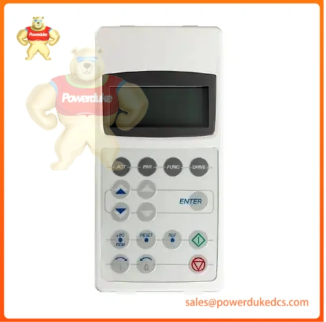
The ABB CDP-312R is a digital operator interface module designed for configuring, monitoring, and debugging variable frequency drives (VFDs) and servo systems. It serves as the primary engineering and operation terminal for the legacy ACS800 drive platforms, as well as ACS850 and ACSM1 series drives. The module features a 4-line by 20-character backlit alphanumeric LCD screen and a 16-key tactile membrane keypad, enabling direct access to parameter tables and real-time internal drive variables.
Historically, the CDP-312R replaced the obsolete CDP312 module used on the older ACS600 inverter family.
Technical Specifications
| Parameter | Value / Specification |
|---|---|
| Brand / Manufacturer | ABB Drives |
| Model Number | CDP-312R |
| Product ID / Part Number | 68281059 |
| Alternative / Legacy IDs | 3BHB015055R0001, 61085301, 64378660 |
| Display Type | Backlit Alphanumeric LCD |
| Display Capacity | 4 lines × 20 characters |
| Keypad Array | 16 flat, labeled tactile push-buttons |
| Enclosure Protection | IP54 when panel-door mounted |
| Max. Ambient Temperature | +40 °C (+104 °F) |
| Interface Port | Flat ribbon cable or RJ45 serial connection to drive control board |
| Net Dimensions | 210 mm (W) × 120 mm (D) × 40 mm (H) |
| Net Weight | 0.1 kg (0.22 lbs) |
Commercial Availability & Lifecycle Terms
- Condition: New Original (Factory Sealed). Sourced from clean industrial surplus inventory, retaining all original packaging and static protection.
- Warranty: 12-month physical and operational warranty covering electronic components and panel membrane degradation.
- Lead Time: Ready for immediate dispatch; standard processing time is 1 to 3 business days from receipt of order.
- Pricing Notice:
[!NOTE] Listed prices are indicative of the current surplus automation market. Contact our technical sales team for an updated, firm commercial quotation based on volume and real-time component availability.
Interface Layout & Functional Architecture
The display matrix and physical keys are split into distinct functional zones to accommodate deep-level parameter tuning and live troubleshooting:
Screen Layout Logic
- Row 1 (Status Line): Displays the assigned Drive ID, panel operational status (L for Local, R for Remote), rotational direction (Forward/Reverse arrows), drive running status (I for Running, O for Stopped), and the current speed/torque reference value.
- Rows 2–4 (Data Lines): Displays real-time operational data, active faults, or parameter names and values during editing modes.
Dedicated Keypad Groupings
- Operation Mode Keys: Contains Actual (for live signaling), Parameter (for engineering access), Function (for data upload/download functions), and Drive (for changing target drive IDs when wired across a multi-drop network).
- Drive Control Keys: Provides direct mechanical overrides for commissioning: Start, Stop, REF (Reference value input), Forward/Reverse toggle, LOC/REM (Local/Remote switching), and a hardwired RESET push-button to clear active trips.
Field Deployment & Installation Engineering
Door and Remote Mounting Constraints
While the CDP-312R connects directly to the drive’s control board for standard frame installations, external enclosure panel-door mounting requires a separate platform kit:
- Required Accessories: RPMP-11 or RPMP-13 mounting platform kit containing the gasket seal, mechanical bezel, and flat-to-round serial extension cable.
- Ingress Rating Considerations: The front interface meets IP54 environmental constraints only when the mounting gasket is correctly compressed against a smooth, unwarped enclosure surface. Deformed panel doors or loose mounting clips compromise the seal, risking ingress of fine industrial dust or moisture which can short-circuit the internal logic board.
Multi-Drop Drive Networking
When using a single CDP-312R to manage multiple ACS800 drives via an RS-485 network arrangement:
- Ensure each drive control board is assigned a unique node ID in the parameter index before removing the localized panel.
- The maximum allowable cable length for the serial trunk depends heavily on electromagnetic interference (EMI) levels inside the cabinet. Run data cables separate from high-voltage 3-phase motor output lines to prevent data packet corruption and communication dropouts.