Description
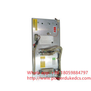
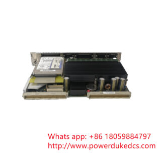
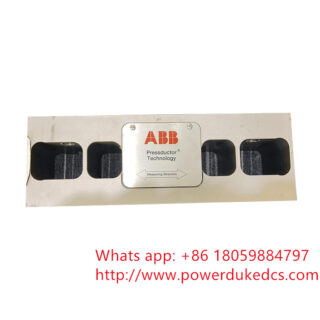
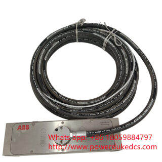
The 3BHB023302R0001 is an ABB high-power semiconductor assembly utilizing an Integrated Gate-Commutated Thyristor (IGCT) topology. This device is engineered for medium-voltage (MV) power electronics applications, serving as a primary switching element within ABB’s high-capacity variable frequency drives (such as the ACS6000 and ACS5000 series), wind power converters, and Flexible AC Transmission Systems (FACTS).
By integrating the gate drive electronics directly onto the semiconductor housing, the IGCT achieves fast turn-off times and minimal conduction losses, combining the high current-handling capability of a standard thyristor with the fast switching features of a transistor (IGBT).
Technical Specifications
| Parameter | Specification / Value |
| Brand | ABB |
| Part Number | 3BHB023302R0001 |
| Device Type | Integrated Gate-Commutated Thyristor (IGCT) |
| Application Layer | Medium-Voltage Variable Frequency Drives & Power Inverters |
| Gating Control Interface | Optical/Fiber-optic triggering input |
| Power Interconnect | Press-pack design for uniform thermal and electrical clamping |
| Cooling Method | Water-cooled or high-airflow forced convection heat-sink mounting |
| Environmental Protection | Industrial-grade protective coating on integrated driver PCB |
Field Application and System Integration Notes
Press-Pack Clamping Force Requirements
The 3BHB023302R0001 is a hockey-puck style press-pack component that requires precise mechanical force to establish electrical contact and minimize thermal resistance.
- Clamping Pressure: When installing the module into the drive phase leg, you must use a calibrated hydraulic or mechanical clamp. Under-clamping introduces local high-resistance hotspots that lead to thermal runaway under heavy load profiles, while over-clamping will permanently crack the fragile internal silicon wafer. Refer to the specific drive manual for the exact kilonewton (kN) clamping rating.
- Surface Preparation: Clean the copper contact surfaces of the heatsink thoroughly. Apply a microscopic, uniform layer of high-conductivity thermal paste to ensure maximum heat dissipation.
Fiber Optic Gating and Power Requirements
- Optical Transceivers: The integrated gate driver board receives pulse-width modulation (PWM) commands directly via fiber optic lines. Ensure the optical terminations are entirely free from dust or chemical residue before mating.
- Gate Power Supply: The onboard driver board requires a steady local auxiliary power source (typically derived from an isolated power supply board within the phase module stack). Fluctuations or noise on this auxiliary rail can degrade turn-off capability, risking an internal short-circuit across the phase leg.
Safety Protocols During Maintenance
Because this module handles high voltages and stores substantial capacitive energy:
- Discharge Time Verification: After isolating the medium-voltage drive, wait for the DC link capacitors to bleed down below a safe safety threshold (typically 5 to 10 minutes, verified via internal system instrumentation).
- Grounding: Apply temporary safety grounding straps to the phase outputs before touching the IGCT assembly or loosening the press-pack clamp bolts.
Commercial and Procurement Data
- Product Condition: New Original (Factory Sealed/Surplus) or Refurbished (fully tested with forward/reverse blocking voltage validation).
- Standard Warranty: 12-month comprehensive depot hardware warranty.
- Estimated Lead Time: Typically ships within 3 to 5 business days from central logistics inventory, subject to strict quality control check-out routines.
- Pricing Notice: Price points depend heavily on active factory allocation pipelines, raw semiconductor availability, and specialized test validation requests. Contact our industrial components desk for an itemized, firm commercial proposal.