

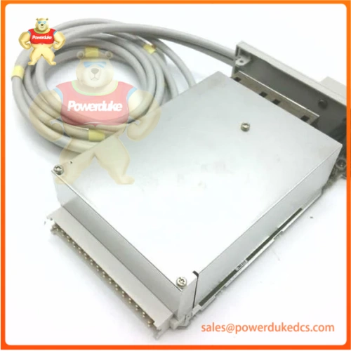
Description
1. Unboxing & Physical Snapshot
- Model & Brand: 6DS1213‑8AA, Siemens TELEPERM‑M legacy DCS bus coupler Eurocard (discontinued inter‑subsystem coupling board for AS620 TELEPERM‑M/ME subracks)
- Physical Dimensions (Approximate W × H × D): 220 mm × 233 mm × 25 mm, standard DIN41612 double‑height Eurocard form‑factor for TELEPERM‑M rack slots
- Estimated Shipping Weight: 1.10 lb (0.50 kg net module weight; includes main PCB assembly, front ejector lever set, dual rear DIN41612 backplane connectors, front‑panel RUN/ERR/BUS status LED bank, OEM printed installation datasheet, static‑shield bag, foam‑reinforced export carton)西门子工业…
- What’s in the Box: Complete 6DS1213‑8AA bus‑coupler Eurocard, front‑panel ejector hardware; TELEPERM‑M host subrack and external bus cabling sold separately (validate hardware revision and EPROM firmware version against existing installed unit prior to procurement. Mismatched coupler firmware will break cross‑subsystem data exchange for power‑plant, chemical‑process and water‑treatment legacy DCS installations).
2. Product Introduction (Structure B – Architecture hook)
This 6DS1213‑8AA TELEPERM‑M plug‑in bus‑coupler Eurocard establishes logical and electrical data links between multiple TELEPERM‑M/ME automation sub‑systems. It routes process values, interlock signals and diagnostic telemetry across the ME‑bus while isolating local backplane traffic from remote sub‑system domains. Dual DIN41612 rear connectors deliver stable electrical contact to the subrack backplane bus. Poor insertion, bent pins, or firmware incompatibility trigger partial data freeze‑ups, missing alarm telemetry and silent interlock‑signal corruption that mimic CPU or backplane faults within high‑availability continuous‑process production strategies.
Reliability teams must validate full part‑number and hardware‑firmware revision prior to spare rotation. Other TELEPERM‑M Eurocard variants share the same mechanical footprint but implement different bus‑coupler logic and addressing rules. A dimensionally‑compatible mismatched board fits the rack slot yet cannot properly translate inter‑subsystem bus telegrams, leading to total cross‑domain communication collapse. No software‑parameter adjustment can compensate for hardware‑firmware protocol mismatch.
3. Core Technical Specifications
| Parameter | Value |
|---|---|
| Module Type | TELEPERM‑M / ME inter‑subsystem bus coupler Eurocard |
| Backplane Interface | Dual DIN41612 male connectors for TELEPERM‑M subrack bus |
| System Bus | ME‑bus coupling interface for multi‑subsystem linking |
| Status Indication | Front‑panel RUN / ERR / BUS diagnostic LED indicators |
| On‑board Memory | EPROM for coupler firmware; RAM for telegram buffering |
| Rack Supply | 24 VDC powered via subrack backplane |
| Mounting | Eurocard slide‑in for TELEPERM‑M standard subrack slots |
| Operating Ambient Temperature | 0 °C to +60 °C (cabinet ambient air) |
| Storage Temperature Range | −40 °C to +85 °C, non‑condensing |
| Form Factor | Double‑height Eurocard; IP00 (cabinet‑rack‑mount‑only installation) |
| Conformal Coating | Standard non‑coated OEM construction |
4. Global Compliance & Industry Certifications
- CE Mark aligned with EMC and low‑voltage equipment directives
- UL/cUL Listed for legacy industrial DCS rack‑mount hardware
- CSA certification for North American cabinet deployments
- ATEX / IECEx Zone 2 qualification for eligible production lots
UL listing validates surge‑withstand and noise‑immunity performance for electrically noisy power‑plant and chemical‑plant environments. Verify specific‑lot certifications against OEM hardware documentation. Bus‑coupler spare parts must retain full date‑code traceability for periodic plant compliance audits.
5. Long‑Term Storage & Asset Preservation Guide
Store this TELEPERM‑M bus‑coupler board sealed inside its original ESD‑shield bag for warehouse shelf storage. Open static pouch exclusively at a properly‑grounded ESD workstation. Unprotected fingertip contact leaves ionic residues accelerating PCB trace and gold‑plated backplane‑pin corrosion.
Maintain storage‑vault relative humidity below 60 %, non‑condensing. Sustained high‑humidity exposure degrades on‑board electrolytic capacitors and bus‑interface signal circuitry. Extended shelf‑life storage requires bench burn‑in and bus‑simulation testing before field deployment to uncover aged‑component degradation.
This assembly contains no user‑serviceable lithium backup battery; coupler firmware resides in soldered‑on EPROM devices. Every 18‑months inspect rear DIN41612 connector pins for oxidation or mechanical bending; deformed pins produce partial‑contact, intermittent cross‑subsystem communication faults.
6. Physical Installation Prerequisites
Execute lock‑out‑tag‑out procedures; fully de‑energize the complete TELEPERM‑M DCS subrack and all connected ME‑bus segments. Operate front ejector levers to extract the old module from rack slot. Align replacement 6DS1213‑8AA with slot guide rails; apply even pressure and close both ejector levers firmly to guarantee full rear‑connector pin engagement.
Maintain minimum 40 mm clearance behind subrack cabinet for convection cooling. Restricted airflow elevates component junction temperatures and may induce intermittent bus‑telegram corruption.
Connect cabinet protective‑earth to facility plant ground bus. Separate DCS signal cabling physically from high‑power motor and switch‑gear wiring to minimise EMI coupling. After hardware replacement, power‑on subrack, confirm module status indicators, download DCS project configuration, validate cross‑subsystem process‑value exchange, alarm propagation and interlock‑signal hand‑off before returning the DCS multi‑subsystem environment to live production duty. Hot‑swap module insertion‑removal is not supported.
7. Buyer’s FAQ
Q: What Harmonized System tariff code applies to 6DS1213‑8AA for cross‑border shipments?
A: This legacy Siemens TELEPERM‑M DCS coupler board maps to HS 85389091 for industrial‑control electronic sub‑assemblies. Customs inspectors commonly require full part‑number plus hardware‑revision documentation. Confirm classification cooperating with your import broker before tendering freight.
Q: How does Country of Origin impact audit acceptance for this end‑of‑life TELEPERM‑M spare?
A: Plant audit checklists cross‑reference nameplate Country‑of‑Origin markings against site‑approved asset registers. Parallel‑sourced spares carrying mismatched COO markings trigger formal audit observations, even when bench bus‑simulator testing appears satisfactory.
Q: Should supplementary shipping insurance be purchased for this obsolete 6DS1213‑8AA coupler‑board spare?
A: Yes. Transit shock may bend delicate DIN41612 rear pins or induce unseen PCB micro‑cracks. Many internal defects are not visible via superficial visual inspection. Secure full‑value all‑risk coverage; standard carrier cargo terms exclude hidden damage to legacy Eurocard‑form‑factor electronic hardware.
Q: Does the delivered 6DS1213‑8AA ship pre‑loaded with site‑specific DCS cross‑subsystem routing parameters?
A: Factory‑sealed OEM units carry base coupler firmware only. All site‑specific bus‑address assignments, telegram‑routing tables and inter‑subsystem filter rules reside within the TELEPERM‑M host‑system project and are not stored on this coupler board. After replacement, download full project configuration and validate end‑to‑end cross‑subsystem signal flow before placing spare hardware into live‑process duty.






