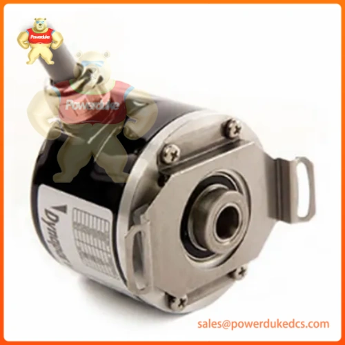
Description
The Reliance Electric WR-D4007 (also classified under hardware drawing number MCPS or MCPS2) is a high-performance industrial power supply card engineered for the PSC5000 and PSC7000 control systems. The module converts incoming alternating current into stabilized low-voltage direct current rails required to run internal rack processors, communication modules, and field-side interface cards.
Commercial and Availability Status
- Condition: New Surplus (In Original Box) or Refurbished (Fully Load Tested)
- Availability: Discontinued by Manufacturer; legacy warehouse stock available
- Warranty: 12-Month Comprehensive Warranty
- Lead Time: Ships within 2–4 business days from allocation testing
- Pricing Note: Price is influenced by limited regional availability for older Reliance legacy parts. Contact our technical procurement desk for an active, firm quote.
Technical Specifications
| Parameter | Value / Specification |
| Manufacturer | Reliance Electric / Rockwell Automation |
| Model / Type | PSC Power Supply II (MCPS2) |
| Part Number | WR-D4007 |
| Supported Platforms | PSC5000 / PSC7000 Controller Frame |
| Input Voltage Range | 85 to 132 V AC or 180 to 265 V AC (Auto-ranging or configuration specific) |
| Input Frequency Range | 47 to 63 Hz |
| Main Output Voltage | 24 V DC (Regulated, filtered) |
| Continuous Output Current | 5 A to 7 A maximum (Configuration dependent) |
| Peak Load Capacity | Up to 10 A short-duration surge |
| Response Time | \le 1 ms dynamic load compensation |
| Protective Circuitry | Overcurrent clamp, overvoltage shutdown, short-circuit protection |
| Operating Temperature | −20 to +60 °C (−4 to +140 °F) |
| Weight | Approximately 2,000 g (2.0 kg) |
System Integration & Power Sizing Mechanics
Load Balancing Across Racks
The WR-D4007 functions as the primary power engine for the local PSC platform backplane. When executing field layouts alongside digital input/output cards (such as the S-D4006 DIO-1) or analog modules (such as the S-D4008 AIO-1), calculations must be performed to guarantee total internal current consumption does not exceed the continuous output ceiling of the supply. Overloading the module initiates an internal thermal foldback state, dropping the 24 V DC rail and dropping the attached processor into a fatal halt configuration.
Redundancy Operations
The MCPS2 architecture supports parallel or active-redundant power configurations. When paired on a shared chassis utilizing an auxiliary diode-steering matrix, two WR-D4007 modules dynamically balance total system load distribution. If an internal component failure occurs within one supply, the companion unit carries the aggregate system demand without dropping backplane potential or disrupting active cyclic execution.
Installation Parameters and Grounding Protocols
- Enclosure Dissipation: The unit relies heavily on passive convection cooling. Maintain a minimum clear boundary space of 50 mm above and below the card chassis to prevent heat loading on adjacent processing units.
- Low-Impedance Bonding: Due to electrical switching noise common in power electronics, a heavy grounding strap (\ge 2 mm^2 or 14 AWG) must connect the dedicated structural grounding terminal directly to an isolated copper master ground bar. Improper chassis bonding increases high-frequency ripple voltage across the 24 V DC bus, leading to logic parity data errors on adjacent communication cards.
- Pre-Power Inspections: Ensure that terminal terminal blocks are properly torqued and that line voltages fall safely within the specified nominal ranges (85–132 V AC / 180–265 V AC) before energizing. Swapping or hot-jacking input power plugs while under full load risks arcing internal contact paths and damaging input stage rectification filters.