

Description
1. Unboxing & Physical Snapshot
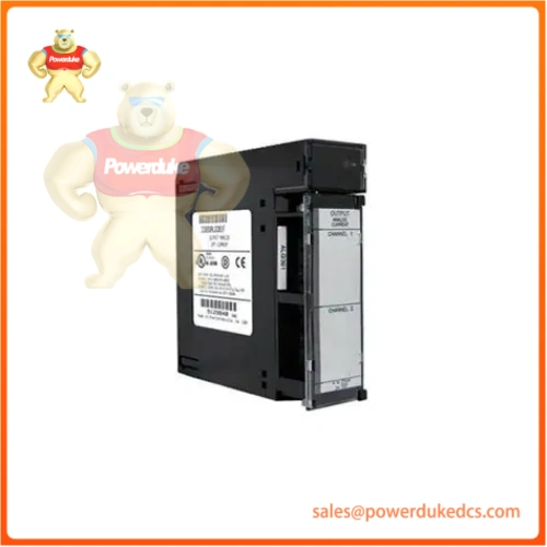
- Model & Brand: GE Fanuc / Emerson Series 90-30 FIP Bus Controller Module — Part Number: IC693BEM340
- Physical Dimensions: Standard Series 90-30 single-slot module profile (Approximately 145 mm H × 35 mm W × 125 mm D)
- Estimated Shipping Weight: Approximately 0.40 kg (Packaged in multi-layer anti-static bubble containment and rugged corrugated transport boxing)
- What’s in the Box: IC693BEM340 FIP bus controller module card, captive mounting screws, front status indicator panel, and manufacturer technical specification sheet.
2. Product Introduction
Structure B (Architecture hook): Engineered to link GE Series 90-30 PLC architectures with high-speed Factory Instrumentation Protocol (FIP) field networks, this bus controller module slides securely into any standard baseplate slot. Within distributed industrial automation control networks, it manages deterministic data exchange between the central PLC processor and remote I/O drops without introducing system bus latency.
Housed in a sturdy industrial polymer and metal-shielded enclosure, the internal communication processors resist continuous plant floor electromagnetic interference and mechanical shock. Its dedicated diagnostic LEDs provide real-time status reporting on bus health and communication traffic, allowing control technicians to isolate network anomalies instantly during troubleshooting windows.
3. Core Technical Specifications
| Parameter | Value |
| Module Type | FIP Bus Controller Module |
| Product Series | GE Fanuc / Emerson Series 90-30 PLC |
| Network Data Rate | 1 Mbit/s FIP communication speed |
| Slot Requirement | Single slot (Compatible with standard Series 90-30 baseplates) |
| Backplane Power Consumption | 1.2 A typical at +5 VDC |
| Communication Interface | FIP network trunk line via screw-terminal or pluggable connector block |
| Operating Temperature Range | 0°C to +60°C (32°F to 140°F) |
| Storage Temperature Range | -40°C to +85°C (-40°F to 185°F) |
| Physical Net Weight | Approximately 0.35 kg to 0.40 kg |
4. Global Compliance & Industry Certifications
Type-test verification and regulatory compliance documents are mandatory for system integrators auditing high-availability industrial network architectures.
- Expected Certifications: CE Mark (EMC and Low Voltage Directives), UL/cUL Listed Industrial Control Equipment, and RoHS material compliance.
- Safety Relevance: Rigorous electromagnetic compatibility (EMC) testing ensures that high-frequency communication bursts across the FIP network lines will not induce stray voltages into adjacent analog measurement cards.
- Audit Note: Cross-verify firmware revisions and network node address configurations against your PLC hardware configuration file (
.conf) before inserting the card into active backplanes.
5. Long-Term Storage & Asset Preservation Guide
Veteran Maintenance Note: Storing communication network interface modules in unconditioned industrial warehouses requires strict humidity and electrostatic protection to prevent edge-connector oxidation.
- ESD Control: Keep the communication module permanently sealed inside its original metallized anti-static shielding bag to protect sensitive internal CMOS interface transceivers from electrostatic discharge.
- Climate Baseline: Maintain warehouse storage relative humidity strictly below 50% non-condensing to prevent atmospheric tarnishing of the gold-plated backplane connector pins.
- Physical Protection: Store modules flat or vertically slotted in dedicated foam bins; avoid stacking heavy inventory directly on top of the module housing.
6. Physical Installation Prerequisites
- Ensure rack backplane power is fully switched off before installing or extracting the module to prevent electrical arcing across sensitive bus pins.
- Align the card carefully with the top and bottom rack guide slots, pressing firmly until the rear connector seats completely into the backplane bus.
- Fasten the top and bottom securing screws firmly to anchor the chassis against vibration-induced loosening in industrial cabinet environments.
7. Buyer’s FAQ (Logistics & Compliance Focus)
- What Harmonized System (HS) code governs international customs clearance?The standard global export classification for this communication controller module is 8517.62.0050 (Machines for the reception, conversion and transmission or regeneration of voice, images or other data).
- How does Country of Origin (COO) verification impact trade compliance?Accurate origin tagging on commercial export documentation ensures compliance with international trade agreements; check the factory mark on the product label (typically United States manufacturing origin).
- Does this hardware require custom configuration files?Yes, system programmers must configure the FIP bus parameters, bus addresses, and scan lists using programming software (such as VersaPro or Proficy Machine Edition) during project integration.
- What level of transit insurance should be specified?Always mandate fully declared-value, tracked air cargo insurance to safeguard against drop impacts and mechanical shock during international transit.






